


Starship 2D Design Tutorial
People keep asking me how I draw my starships. I will try to answer the question with this tutorial. It describes the basic techniques from a simple sketch to a fully-fledged image with pseudo-3D effects. The description is specifically for iGrafx (Micrografx) Designer, but the principles should be applicable as well to other software like Corel Draw, Adobe Illustrator or Freehand. Read about my experiences with three of the four programs in my review. There are probably many more different recipes to accomplish the same goals which I can't all present on this page. If you're doing 2D design yourself and have some remarks or tips, I'm looking forward to your feedback.
Notice You may notice that I made this tutorial based on the German language version of iGrafx Image, so some names of the tools and menus I translated back may not be the same as they are in the actual English version. If you find something that should be corrected, please contact me.
From a Hand-Made Sketch to a Line Drawing
The design of the Fabrux-class starship starts with some scanned sketches Lance Nutter sent me in 2000. They can be seen on my page dedicated to the Fabrux. I liked the ship so much that I decided to create a three-view 2D design of it.
Preparing the sketch
I usually start drawing Federation ships with a side view. Once the rough outlines are ready, I draw a saucer, secondary hull and nacelles to see what the top view would look like. In the case of the Fabrux, Lance took care of almost everything, so a long try-and-error process was not necessary. I just had to redraw the already quite precise side view he had provided. First of all, I had to rotate the sketch in a pixel imaging program until it was perfectly horizontal. The image could then be copied to the clipboard and pasted into Designer.
Defining the size
The size in Designer is always arbitrary, because each image is assigned a certain resolution in dpi independently of the actual size in pixels, and Designer has a certain page size in centimeters (or inches, if you like that better). The size, however, doesn't matter anyway because I routinely resize the image in Designer to match my user-defined unit. This unit gives me the size of the real ship in meters, and the conversion factor is 42.89 meters of the ship per one inch of the Designer sheet. I'm using this scale for almost six years, and it has "historical reasons" why the conversion factor is so odd. Using rulers with meter units, I don't need a pocket calculator to determine the design size. Furthermore, I can avoid all the fuss with 2m tall decks and ships whose size figures have to be changed afterwards. My ships have 3.5m to 4m tall decks and a definite size from the very beginning. When I design a completely new ship (I usually don't use pencil sketches), I stack rectangles of one deck height each and draw my starship port view within this grid.
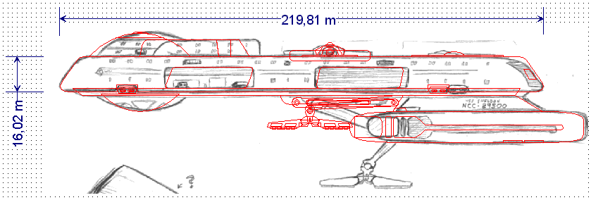
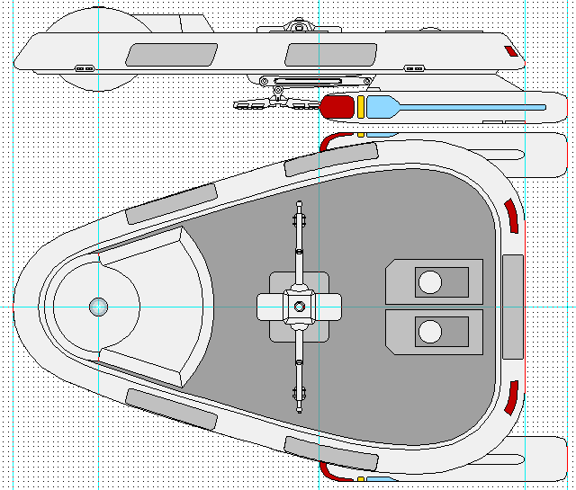
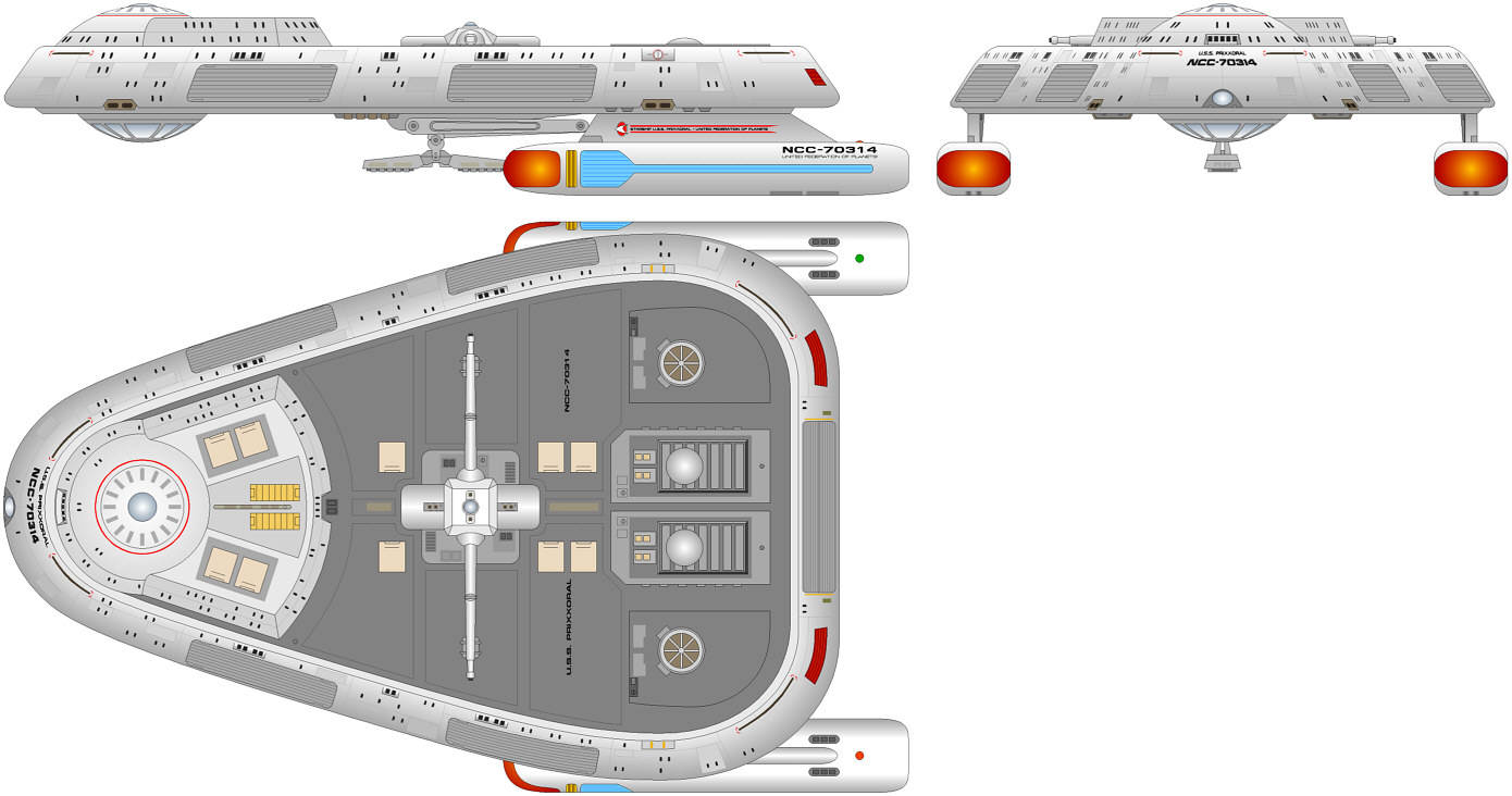
The Fabrux was nailed down to be 220m long (main hull only) and four decks tall in its main body (image).
Choosing an appropriate grid
The most important thing to pay attention to is the grid. Doing it with "snap to grid" disabled is theoretically possible, but you will have to use rulers excessively to draw horizontal and vertical lines and to align things to each other. It may go as far as you have to care more about your ruler maze than about the actual drawing. Therefore adhering to the predefined grid is the much better option. The vertical and horizontal grid should be equal, of course. It may surprise that the drawing will be the more accurate the rougher the grid is chosen! I usually start with 40 grid points per inch, which is only four grid points per deck or about one point per meter in my above drawing scale. With a rough grid, I don't have to zoom too far in when I'm drawing a new shape. I can still see the grid snap even at a full page zoom, and it can't happen that a line looks perfectly horizontal, but is actually slightly tilted. A grid of 1m is absolutely sufficient to draw the basic shapes of a ship which is 200m long. Whenever I need to add smaller details, I can decrease the grid pitch any time. It is obvious that the finer grid must be an integer multiple of the rough grid, so I later switch to 80 points per inch.
Redrawing the sketch
Automatic retracing of the bitmap image is not an option, although the sketch consists of rather simple line structures. The first reason is that retracing tools don't really recognize curves as such. They approximate everything with too many points of which most have to be removed to give me a smooth curve again. Drawing a new curve by hand can be done much faster. Secondly, all the inaccuracy of the bitmap would stay the same or get even worse. A retraced sketch would be either too rough, or lines wouldn't be exactly straight and horizontal, although they should be. Finally, and this is the most important point, retracing is capable of creating closed shapes, but almost never the desired closed shapes. Since everything has to be pulled apart and reassembled anyway, it is better to draw completely new objects.
I retraced the complete image manually (image). While doing this, it is recommended to lock the pixel image, because accidentally double-clicking it would open the bitmap editor, and this OLE operation sometimes crashed the program. It may work better elsewhere. Anyway, it is annoying to suddenly see the bitmap editor window.
To redraw the image, I use hair lines, i.e. lines with a width of 0pt, and with few exceptions I keep them that thin until the end. The reason for drawing everything with thin lines is that this is how real technical design is done too and that it's much more precise. I can recognize off-grid or open shapes that should be closed immediately when drawing with thin lines. Since Designer still has problems with rendering thicker lines which often appear extremely rough, I use thick lines only for things like phaser strips or hull markings, while the rest of the hull entirely consists of hair lines.
Using simple shapes
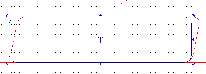
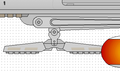
I draw simple shapes such as circles, ellipses and polylines whenever possible. The example of the lower manipulator (image) shows that only simple closed polylines and a few circles were used. Maybe if it is a larger object, or if we are supposed to have an even closer look at it, the shapes should have rounded corners, but here it was sufficient to leave the sharp corners, especially since it was going to be a rather small web image. The manipulator arm consists of rounded rectangles which were first tapered and then rotated by a few degrees. Since the finalized arms wouldn't need to have a point in the grid anyway, I switched off "snap to the grid" when modifying them. Without the grid it is necessary to zoom in very far when adjusting shapes relative to each other.

Using as few points as necessary
When drawing and modifying polylines, it is crucial to add as few points as necessary to form a curve. Every additional point will make the curve look more wavy, because each curve point has its individual tangents which define the curvature in this very point. Matching many tangents to yield a smooth curve is difficult and mostly not necessary. Even if it doesn't look so at the first glance, every curve which doesn't change its direction can be drawn with only two end points and tangents. The example of the nacelle tip (image) shows how a simple shape, in this case a box with a circle segment at the left end and two rounded corners at the right end, was defined by as few points as possible and necessary. In this case seven points were required: One for the circle curvature, two for the two corners between the circle and the rest of the box, and two for each rounded corner. The advantage of a rough grid is that I could have easily drawn this shape without the help of the rulers (shown in cyan), since counting three or four grid points to make the upper and lower half identical is quite easy. Another option would be drawing only the upper half and complete the shape by mirroring and closing it. This is much faster in case there are many points that have to match.
Modifying shapes
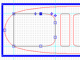
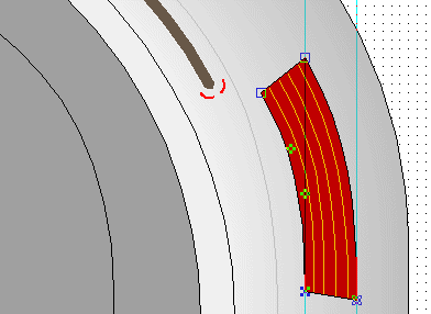
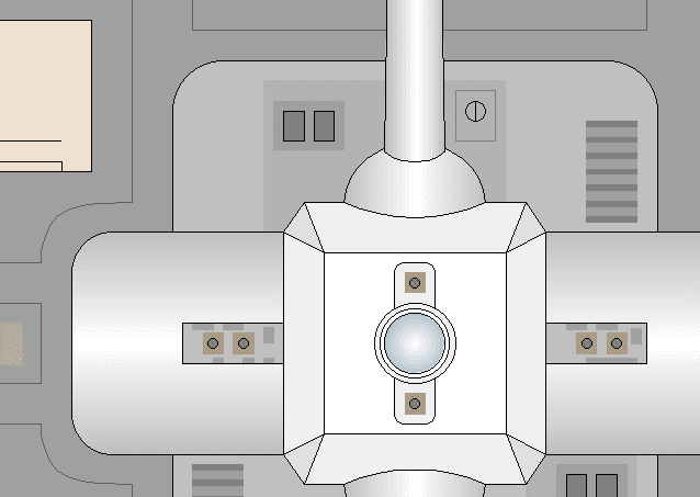
Modifying an existing shape can be almost as prolific as drawing a new one from scratch. The first example shows how a circle was modified to an open or closed circle segment. Designer, as opposed to other software, has plenty of possibilities to draw a circle, and it would be feasible to directly draw a circle with the final size in the final location. Anyway, it doesn't matter how the circle is created in the first place. It is only a bit more work to draw the circle somewhere else, resize it to the desired size and move it to its destination. Double-clicking the circle and moving the two end points along its perimeter allowed me to "cut off" a sector (image). I used a ruler to ensure that both ends were at the same height, so the secant I drew to close the circle would be exactly horizontal. Well, I noticed that, although the ruler was in the grid, the two end points were not. So I had to "cheat" a bit and stretch the circle segment until the secant was in the grid again.
Inclining a box is one of the easiest modifications. In Designer and Corel Draw it just needs to click the box twice (not too fast, because that would be a double-click). In this case the box (the shuttlebay door) was rounded (image). It would have been a very bad idea to first incline the box and then try to add rounded corners, because that's a lot of work once it is a parallelogram and not a rectangle any longer. The modification can be done either in the grid, to ensure that the upper edge will stay in the grid. Alternatively, the upper edge can be moved along a ruler, so the grid can be disabled. Sometimes the precision of inclining within the grid is sufficient, though.
Sorting the objects
Before coloring the design it has to be ensured that all shapes are closed and that they are arranged in the correct order from the background to the foreground. If this is not true, it may happen that some smaller shapes disappear behind the large hull once the hull is filled. I usually don't like drawing shapes without filling, since such objects can only be moved or modified if I exactly hit their border, and I can't see which of them lies in front of another one. Anyway, if a bitmap has to be redrawn, it is obviously necessary to work with transparent shapes. I frequently check their order by selecting the whole drawing and assigning a fill color, so I can see if small objects vanish. In such a case I move the larger shapes further to the background. As for smaller objects which are not in the correct order, they may be sorted more easily any time.
Applying colors
Once the object arrangement is correct, coloring the drawing is very easy. In the case of a Federation starship I begin with some basic colors for the hull, usually shades of gray like RGB (192,192,192), RGB (240,240,240), etc. It is intentional that there is not much difference between the gray tones I use. More contrast could let them look like "comic style". The blue plasma glow is RGB (144,216,255), the Bussard collector basic color is RGB (192,0,0). I usually reserve the effects like color gradients until the very end of the design. This is a custom I had to practice on my old 486 anyway because the effects slow down the display considerably. Another reason is that the effects have to be harmonized with the hull details.
Matching different views
Drawing more than one elevation of the same object is pseudo-3D design. Corresponding points in different drawings must match with one another, but verifying this is very difficult. There is no predefined method, let alone a special tool for that, and it is up to the designer (the one with the small "d" ;-)) to accomplish it with lots of rulers, complicated rotating, resizing and mirroring operations and a good 3D sense. Actually, while there is a lot of redundancy in real 3D design in that a 3D shape is complete once for all, it is a lot more work drawing three 2D views of a starship that correspond with each other than drawing three independent 2D views, since everything has to be measured and critically considered again and again.

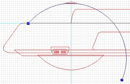
Basically, each single edge has to be transferred from the side view to the top view using a vertical ruler. It is obvious that too many visible rulers get confusing, and that the structures of the top view have to be drawn one at a time. In some cases it is easier to copy whole parts of the side view, and take them as a basis for the shapes in the top view. The nacelles (image), for instance, look similar from the top and from the side, and it usually takes only a few modifications to create the top views. Since the top view is always symmetrical (I haven't tried a Breen ship yet), basically only one half of the shapes needs to be drawn. I always use a horizontal ruler or locked line to mark the symmetry axis. If the shape is complex, however, one half is not sufficient to create an impression of the whole shape. The triangular main hull of the Fabrux is the result of try and error. I drew the upper half, duplicated and mirrored it. While I was not yet content, I deleted the lower half, and modified the upper half again. It was not before I was absolutely sure I had the final shape that I merged the two halves to one.
The example of the oblique shuttlebay door (image) demonstrates how one view determines the look of the other view. The left and right edges of the shuttlebay door should be exactly vertical when looking straight at the side wall. The side view of the ship, however, shows the wall from an oblique horizontal angle of about 20°. This is why the shuttlebay doors must be rotated rectangles in the top view and inclined boxes (parallelograms) in the side view. It is obvious that, in order to determine the correct slope in the side view, it is better to draw the simple, accordingly rotated rectangle in top view first, and transfer the four x-coordinates of the four corners to the side view.
The same is necessary for structures which are straight in one view, but curved in the other one. The additional difficulty is that the curve has to match too. As already mentioned above, it is essential to use as few points as necessary to draw a curve. In the example of the impulse drive exhausts (image), I had to determine the four corner points first, before I tried to match the curvature without adding any more points. The image shows an intermediate result, as the left (upper) outline is still not perfectly concentric with the hull curvature.
Adding Effects and Details
Color gradients
Normal linear color gradients as they are predefined by the program are easy to apply. I always assume that the light is coming almost straight from above. I choose plain white RGB (255,255,255) or very light gray RGB (240,240,240) for the areas that directly face the light source. The advantage of white is that the contrast to the shaded parts is better without the necessity to render the ship too dark. The contrast can still be changed in the pixel editor anyway if the image seems to bright for the web. The color gradient of the main hull (image) goes from white to RGB (192,192,192).*
* Note that the actual gradient in the vector image has no steps, but was only dithered to be displayed as a GIF.
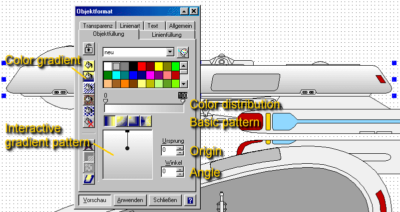
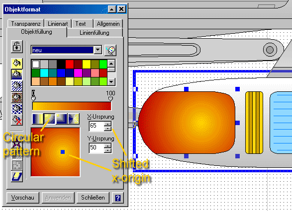
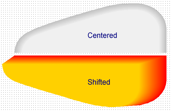
A color distribution with a bright area in the middle and darker areas at the edges can be created by moving the x- or y- origin of the linear gradient, such that the origin, along with one of the two edge colors, shifts to the middle. If the gradient is still linear, this will look like the side of a cylinder. Since the nacelles are actually flat on the top (image), this wouldn't give the correct 3D impression. In order to rectify the impression, I added color points to create a uniform color area in the middle of the pattern. The two edges at 0% and 100% are RGB (192,192,192), while two points at 25% and 75% are white, thereby generating a uniform white area between the two latter points. Thanks to Masao for the hint!
The next example shows a radial color gradient as it is required for the glow of the nacelle tips (image). To make it look more realistic, the x-origin should be moved out of the center of the shape. The colors are brick red RGB (192,0,0) and dark yellow (255,208,0).
Color transitions
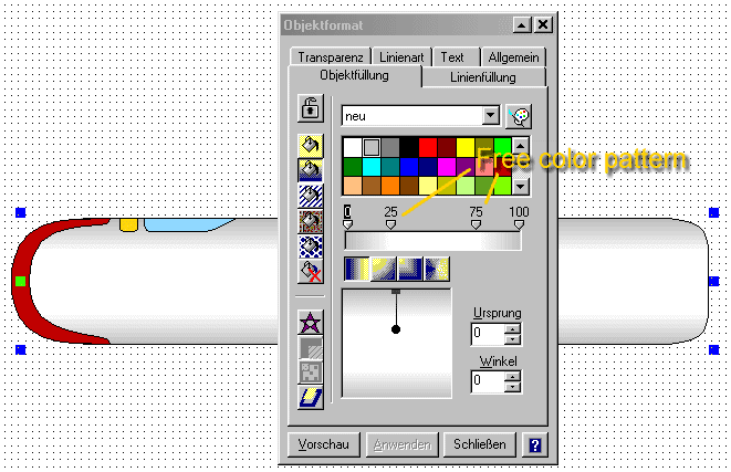
In some cases a color transition can't be created with a color gradient because the tool only works for simple linear or radial transitions. The color transition of the main hull in the top view, for instance, would need to follow exactly the rounded triangular shape (image). In this case the "blend" effect is very useful. It creates a gradual transition from an inner shape to an outer shape, and the precision in terms of the number of steps can be adjusted. This effect, which always worked better in Corel Draw, was improved in the latest version of Designer, and even an interactive blending is possible such that the effect is recalculated once one of the two objects is moved, as can be seen in the lower half of the image. It is important to remove the outlines of the two objects since otherwise they would be multiplied as well. To add the outlines again, I duplicate the innermost and the outermost shape, and simply remove the fill pattern.
For some unknown reason, the blend effect isn't homogenous from the inner to the outer shape any longer whenever the image is reloaded. I tried several methods, including splitting the shapes to an upper and a lower half as in the image above, but it didn't help. This is obviously one more bug of Designer 8. If I, however, move one of the shapes and press "undo", the effect looks as it should again. That's very strange.
Text effects
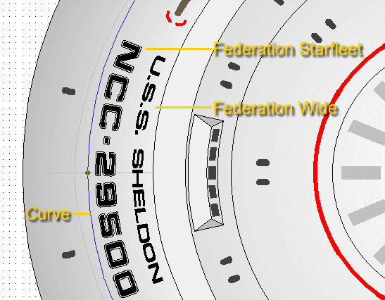
Straight text is not critical at all, but as soon as there is a certain viewing angle, it has to be distorted. Fortunately, in newer Designer versions, the text remains editable (important if a fleet of ships is going to be built ;-)). In many cases, like on the saucers of Federation ships, or at the front tip of the Fabrux class, the text has to follow a curved line (image). I usually don't use a line that already exists, but I make a copy or draw it from scratch. Note that the curve doesn't have to exactly correspond with the curvature of the hull, for the text is somewhat irregular. It is rather important to center the text. The fonts for TNG era ships, by the way, are Federation Wide for the name and all small registry numbers, and Federation Starfleet for the main registry number. The latter should have a thin red outline, but in this case the font size was just too small to add an outline, considering that the number will be just readable on the web image.
Adding details
I sometimes used lines with a width of 0.5pt or 1pt for the windows, but turned to closed shapes with a filling and without outline lately because these scale with the drawing. The fill color is dark gray RGB (64,64,64). If the viewing angle is not straight, the windows have to be turned or inclined, and this works a lot better with the closed shapes which were originally rounded rectangles. Exaggerated precision is not required, but if there are several windows in a row, they should have an equal slope if they are close to each other, and there should be a tendency to greater slopes as more as the viewing angle deviates from the straight view.
Every 24th century Federation starship, even if the studio model is not that detailed, can be supposed to have a deflector grid, transporter emitter pads, lifeboats, lots of small sensor pallets, airlocks and several unidentified details. It is rather easy to add them, especially since they are often visible in only one of the orthographic views. However, there shouldn't be too many of them and they should be strategically placed such that the hull doesn't look "speckled".
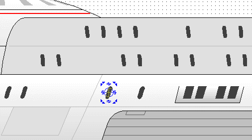
Finally, a nice measure to add more depth and more detail is using areas of slightly different colors. The Enterprise-E and other newer ships are good examples how a model may look more ore realistic with small color contrasts. I used the same methods for the lower manipulator arm (image).

The decoration, consisting of Starfleet arrowheads, red lines, the ship's name, airlock and shuttlebay signage and occasional small colorful details adds a lot to the overall impression of the ship. Even if the details are hardly visible or readable, they should be carefully designed. After all, they may serve as a template also for smaller ships on which they generally appear larger.
Matching details in different views
Transferring window patterns from one view to another is the most painful work of all, and I'm relieved every time it's over. The procedure is not always the same. In many cases the windows have to be transferred from the saucer top to the saucer side view, and they need to be extremely distorted to fit. In the case of the Fabrux there were "only" four rows of windows to be copied from the side view to the top view (image). It is crucial that only one row is transferred at a time.
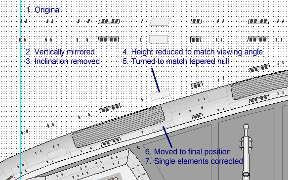
The following numbers refer to the steps in the above image.
1. The first thing to do is selecting all the structures to be copied at once and duplicate them holding down the CTRL key. If more objects have been duplicated, they can easily be removed after everything has been dropped in an empty region. If there's something missing in the duplicate, it is easier to delete everything and do it once again than trying to insert the missing window.
2. Sometimes the whole structure has to be mirrored, like in this case, where the port window rows are transferred to the starboard side of the top view. I take the starboard side because it's closer to the side view considering that I need to zoom in and out and compare dozens of times until all the windows are correct.
3. The windows which I inclined to match the viewing angle of the side view have to be straight in the top view. Since the inclination is not exactly the same everywhere, I have to mark smaller groups of windows. It doesn't have to be very precise considering that the window height will be lowered and the windows will be turned anyway. The grid has to be disabled for this step, and a ruler should ensure that the height stays the same.
4. The window height appears to be only lower in the top view, so it is accordingly reduced to about 70%. Again, this doesn't require the highest precision, but it has just to be ensured that with four rows of windows the windows of two different rows or decks don't touch each other.
5. The window row is now rotated to match the tapered shape of the main hull. Since I usually don't measure or calculate angles, I simply try until I find the correct angle.
6. Now is the last chance to group the windows to one object. In case I accidentally lose the selected windows while they are above the main hull, it may take several minutes until I have re-selected exactly all the windows to be moved and nothing else. When I move the window row to its final position, I have to switch off the "snap to grid" option and zoom in very closely. The only point of correspondence I need is the left (or right) edge which I have marked with a ruler.
7. Considering that the hull front and aft ends are curved, it is necessary to correct windows located in these areas separately. Even if the hull flanks were perfectly straight, some windows might have to be corrected as well, considering that the preceding steps all had to be done without the help of the grid and, moreover, involved inclining and rotating.
Bitmap conversion
Converting the image to a bitmap is a pain in the a$$ with Designer as I have already criticized in my software test. The only viable way (of four altogether) is to convert the whole drawing to an image while it is still on the Designer worksheet. Be sure that you convert a duplicate to an image! The anti-alias/smoothing option is not as good as in Corel Draw, for instance, and it only works up to 400dpi. Beyond 400dpi, the lines have harsh color transitions and oblique lines are stepped. In the case of the Fabrux, 300dpi were sufficient anyway. I chose 300dpi and anti-alias, copied the image to the clipboard and pasted it into my pixel editor, iGrafx Image in this case. In the pixel editor I corrected gamma to 0.6 so as to get a darker and more contrasting image, and I resampled the image from 2768*1451 pixels to 50%. I sharpened the image to compensate for the resampling effects. The final result was converted to a JPG with 6% compression and 147K size.
See Also
Fabrux Class - the page about the design that served as an example here
Miscellaneous 2D Design Tricks - some more useful techniques for 2D (starship) design
Drawing Software Test - reviews of Micrografx Designer, Corel Draw and Adobe Illustrator

Back
to Technical Support index


